You'll need the following measurements for the form that you will be filling out.
We've included a printable PDF worksheet for your convenience.
We've included a printable PDF worksheet for your convenience.
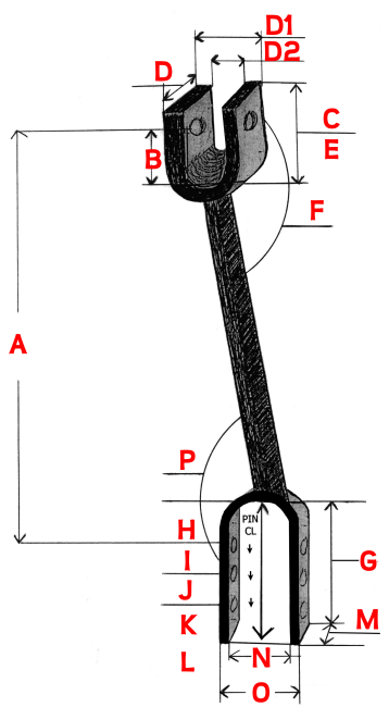
A: Center line length from pin at top clevis to top pin hole of bottom clevis. Measure your stationary side link, usually on
the left side of the tractor
or
A1: If both of your side links are adjustable, the collapsed length and the maximum extended working length (two measurements needed)
B: Center line length from pin at top clevis to inside bottom of top clevis
C: Top clevis total inside depth
D: Top clevis width
D1: Top clevis width outside
D2: Top clevis width inside
E: Top clevis pin diameter
F: Amount of degrees of the top clevis from the side link shaft; is the pin 90° to the side link shaft or something else?
G: Inside total depth of bottom clevis
H: Center line distance of top clevis pin hole of bottom clevis to inside top of bottom clevis
I: Center line distance of second bottom clevis hole from top hole of bottom clevis
J: Center line distance of third bottom clevis hole from second hole (should be same as I)
K: Slot for floating link clevis, contact us if your side link has this
L: Pin diameter size for lower clevis
M: Clevis width
N: Clevis width inside
O: Clevis width outside
P: Degrees of bottom clevis to the side link shaft. A straight clevis would have the clevis pin 90° to the side link shaft. How many degrees is your clevis pin to the side link shaft?
Tractor make
Tractor model
Tractor model
| Worksheet | Submission Form |
Fit Rite Hydraulics